Mary Rosenbaum, OD, Lenka Champion, MD, David Mills, MD
Over the past five years, the eye care professions have begun to recognize the diagnostic value of wavefront analysis in numerous areas beyond refractive surgery. Some of these areas include ocular surface and corneal abnormalities, tear dysfunction, and crystalline and intraocular lens abnormalities, to name a few. But nowhere is the diagnostic application of wavefront science more relevant, universal and of greater potential than in routine refractive care and correction.
The limiting clinical issue in the use of wavefront analysis in refractive care has been the inability to correct the higher order aberrations (HOAs) that are revealed and measured in wavefront aberrometry. The practitioners lament is, What good is it if I can measure something (HOAs) but not correct it?
Practically speaking, this is a clinical frustration and one which has produced diminished interest in wavefront science as a refractive option.
Currently, HOA-correcting lenses are in their first generation with multiple iterations and years of development ahead. However, even today, advancing aberrometry instrumentation combined with practitioner understanding of the integration of wavefront science into diagnostic vision care and correction can lead to a dynamic redefinition of refraction and lens correctionwithout the need for higher order correcting lenses.
Lets examine the standard refraction and apply some basic wavefront principles and instrumentation to it to determine the next level of refractive care and correction. The results can change the way you gather refractive information, analyze it and prescribe corrective lenses from it.
Background Science
Geometrical optics taught us (long ago) that the lower order optics (sphere and, particularly, cylinder) of an eye vary with pupil diameter. Through vector analysis and some complex trigonometric formulas, you can determine the differences in the optical components of a lens prescription through blended cross cylinders and the coupling effect of the cylinder on the spherical component (figure 1).

While the integration of such lengthy mathematical derivations is not practical for a clinician in routine refraction with a manual phoropter, their potential use increases with computer-assisted autorefractors and electronic phoropters. However, the limiting factor in the potential use of the standard autorefractor for vector analysis blended cross cylinder calculations is a fixed, single pupil diameter reading.
Certainly, our increasing knowledge and understanding of the effects on the quality of vision from 3rd and 4th order HOAs at varying pupil diameters, combined with varying lower order changes, adds some frustrations to refractive care. Such a combination of variables, while apparent to clinicians, seems insurmountable in the science of refractive care and correction.
This perceived dilemma has now been addressed through clinical research and a specialized instrument, the 3D Wave by Marco Ophthalmics, a wavefront aberrometer with unique refractive capabilities. Its capabilities include:
Automated refraction for lower order measurements through optical path difference (OPD) calculations.
Wavefront aberrometry for HOA measurements through dynamic spatial skiascopy.
Individual and combined Zernike polynomials in root mean square deviation units (RMS) and point spread function (PSF) maps.
Through a process of three highly accurate, yet quick and efficient steps, this unique wavefront aberrometer, coupled with electronic phoropter technology, provides a new level of accuracy in refractive measurements and lower order correction without the need for higher order correcting lenses.
The steps are:
1. Standard autorefraction.
2. Custom Wavefront Refraction (aberrometry done simultaneously with the autorefraction).
3. The H-D (High Definition) Eye Exam with an electronic phoropter.
Currently, Marco Ophthalmics is the only company producing the combination of technologies that can deliver the Custom Wavefront Refraction (requiring an aberrometer that combines lower order autorefraction with higher order aberrometry measurements) and H-D Eye Exam (requiring a programmable electronic phoropter). As technology continues to evolve in coming years, other companies may also be able to provide this unique and higher level of refractive care.
A discussion of the clinical steps and information from each of the component elements of these procedures introduces a new use of wavefront analysis in the refinement of lower order vision measurements. Furthermore, it introduces the practitioner to a process of optimal and accurate refractive correction with standard, available lower order correcting lenses.
Step One: Autorefraction
How many times have you or your technician conducted an autorefraction only to find that the patient didnt appreciate it as much as their old prescription, or that the results of your manifest phoropter refraction differed slightly or considerably? These discrepancies are due to variable lighting conditions and resultant variable pupil diameters between the autorefraction and manual phoropter examination.
Autorefractors are programmed to capture and calculate lower order refractive readings (sphere, cylinder and axis) at a 2.6mm pupil diameter. This diameter is used to assimilate typical photopic conditions. In a large percentage of patients (up to 80%), as little as a one millimeter increase in pupil size (towards a mesopic/scotopic pupil) will change refractive powers and axis readings. This change is a factor of the circle of least confusion on the retina being increasingly exposed and the higher order aberrations (HOAs) it produces being incorporated into the lower order refraction (figure 2).

This phenomenon of changing refractive power with increasing pupil diameter is not captured by standard autorefraction for two reasons. First, it measures at only one pupil diameter (2.6mm); and second, standard autorefraction does not measure higher order aberrations. The only way such HOA effects can be considered in a refraction would be to calculate the lower order refractive powers at multiple pupil diameters, as well as the respective HOA values (in RMS units) and their associated effects on the lower order prescription. To capture this complex refractive information, the Custom Wavefront Refraction using the 3D Wave aberrometer by Marco Ophthalmics has been developed.
Step Two: Custom Wavefront Refraction
The 3D Wave aberrometer is an instrument that measures, registers and records the lower order measurements of an autorefraction (OPD) at the standard 2.6mm pupil diameter as well as at a 4.0mm pupil diameter (or any other desired, programmable diameter). Simultaneously, the instrument is also measuring the HOAs (aberrometry) in RMS units of each of the respective pupil diameters.
The numerical recordings for each pupil diameter are produced on a thermal tape strip common to all autorefractors. The 2.6mm diameter reported measurements include lower order refractive information in diopters. The second pupil diameters (i.e., 4.0mm) reported measurements include lower order readings (in diopters) plus the HOAs to the 4th order in RMS units. These readings give the examiner the ability to compare the changes in lower order refractive findings for light or photopic (2.6mm pupil diameter) and dim to dark or mesopic/scotopic (larger pupil diameter) conditions. It also provides the RMS information necessary to determine how much effect the HOAs are having on these refractive changes.
The extensive use of aberrometry in refractive surgery has given us a clinical gradient of the effects of RMS values on vision. From this information, it is now well established that, based on pupil size, certain levels of RMS will become noticeable to the patient and produce a qualitative degradation of their lower order vision (figure 3).

When the clinician analyzes these HOA gradient effects in conjunction with lower order refractive information, it produces the potential of refining the final lower order prescription. Such refinements might lead to a decision to introduce a certain degree of bias into a prescription for both photopic and mesopic/scotopic needs, or maybe a lens correction for only photopic or mesopic/scotopic needs. But it can also lead to a judgment and decision of the need for separate photopic and mesopic/scotopic prescription lenses to maximize the quality of vision correction at varying illumination levels.
This extraordinarily valuable information captured in the Custom Wavefront Refraction begins to provide the clinician with a refractive profile on a patient never before achieved, and it begins to answer questions never before understood. For example:
Does this patient have a sufficient degree of change in their photopic versus mesopic/scotopic refraction to require distinctly separate lower order prescriptions (for light and dark conditions) to maximize vision?
Are the changes in RMS values from photopic to mesopic/scotopic conditions minimal or are they significant enough to be causing lower order changes that a customized mesopic/scotopic lower order prescription (in addition to the photopic prescription) might benefit?
Is the influence of the HOA (RMS) component on the mesopic/ scotopic (aberrometry refraction) too great to improve the patients vision quality in dim illumination with any lower order correction?
These questions can now be addressed and evaluated through the Custom Wavefront Refraction and, ultimately, answered through the H-D Eye Exam (discussed below).
The clinician ultimately makes the decision on what will be prescribed from the Custom Wavefront Refraction. However, based on the ophthalmic literature and extensive clinical trials, the software of the 3D Wave aberrometer has been programmed to assist the clinician in deciding between a single or multiple lower order spectacle corrections and/or biasing the prescription to benefit the patient.
Heres How It Works
In the Custom Wavefront Refraction, the 3D Wave simultaneously captures both the photopic 2.6mm pupil standard aberrometry (AR) and the mesopic/scotopic 4.0mm pupil wavefront aberrometry (WF) readings. A thermal tape strip is generated with both of these readings for the clinician to evaluate. The standard autorefraction information is at the top and the WF readings (labeled WF Analysis @ 4.0mm, Ord: 4) are directly below it (figure 4a).
If the sphere and/or cylinder of the AR readings versus the WF Analysis vary by less than +/- 0.50 diopter (sphere and/or cylinder), or the cylinder axis varies by less than 10, it tells the clinician that the patients HOAs (measured by aberrometry) are having little to no clinical effect on the lower order refractive data between the 2.6mm and 4.0mm pupil diameters. Thus, the difference between photopic and mesopic/scotopic vision is subclinical and the mesopic/scotopic (4.0mm pupil) WF data with its blended cylinder is the more appropriate refractive information to consider. Here also, based on the patients needs and history, the clinician might consider biasing the prescription toward either the AR or WF lower order powers.
This evaluation is enhanced through the H-D Eye Exam, where the 3D Wave software programs an electronic phoropter (e.g., Epic, Evolution, TRS) with the appropriate refractive information based on the differences in lower order powers. In this case, with the electronic phoropter, when the sphere and/or cylinder of the AR readings versus the WF Analysis vary by less than +/- 0.50 diopter (sphere and/or cylinder) or the cylinder axis varies by less than 10, the thermal tape will still provide the standard AR data at the top, but the WF data below it will include a statement, WF sent... with an RMS reading at a given mesopic/scotopic pupil diameter (figure 4b).

The WF sent... statement means that the WF data (versus the AR data) has been sent to the electronic phoropter for the H-D Eye Exam. This tells the clinician that the lower order differential between photopic and mesopic/scotopic refraction is not clinically significant and, once again, the WF data with its blended cylinder is the more appropriate refractive information to consider.
However, when the sphere and/or cylinder differential between AR and WF vary by greater than +/- 0.50 diopter (sphere and/or cylinder) or the cylinder axis varies by greater than 10 or the RMS value is above 0.43m, the 3D Wave downloads the AR prescription to the electronic phoropter. Here, the thermal tape will include the statement AR sent... with an RMS reading at a given photopic pupil diameter (figure 4c). In this case, the clinician is being advised and prompted to consider the significant difference in photopic (AR) and mesopic/scotopic (WF) data and refine the AR with a strong possibility of the need for separate photopic and mesopic/scotopic prescriptions.
With this information from the thermal tape, the clinician can now assess both the degree of difference (> +/- 0.50 diopters and/or 10 axis shift) in the lower order powers and axis from the 2.6mm (AR) to 4.0mm (WF) pupil readings, as well as evaluate the RMS effects on the lower order powers at a 4.0mm pupil diameter. If the RMS value is equal or greater than 0.4m, the clinician must begin to consider the risk of compromised quality of lower order vision (figure 3).
The actual difference in the lower order refractive powers between the 2.6mm (AR) and 4.0mm (WF) pupil refractions may provide the clinician with sufficient concerns based on the patients history and needs to warrant separate lens prescriptions for light (photopic) and dark (mesopic/ scotopic) conditions. But, the 3D Wave aberrometer and Custom Wavefront Refraction offer an additional objective measurement to help the clinician further assess and determine the potential value of biasing lens powers or prescribing separate photopic and/or mesopic/ scotopic corrections based on the respective refractive differences.
The point spread function (PSF) is the degree of distortion, or spreading, of a point of light on the retina. This graph is an alternate way of demonstrating Zernike coefficients and, thus, it can reveal unique objective lower and higher order refractive information. The 3D Wave aberrometer provides this in its Wavefront Total and Wavefront HO (HOAs alone) maps (figure 5).

Aberrometry is able to simulate the benefits of a corrected lower order vision by providing the Wavefront HO map and its associated PSF (see figure 5). This reading excludes (effectively corrects for) the dioptric effects of lower order aberrations. Thus, its PSF image represents only the visual distortions associated with the eyes HOA RMS values.
A comparison of the RMS values between the Wavefront Total and Wavefront HO maps (1.663m - 0.319m = 1.344m in figure 5) gives a graphic impression of the effects of lower order aberrations. Even more striking (especially when explained to and viewed by the patient) is the PSF effect (the 1.344m differential in figure 5), which represents the qualitative difference between uncorrected and corrected vision.
Were the patient to have HOAs exceeding 0.4m RMS, the corrected vision (Wavefront HO) would also show observable PSF distortions (spreading). This effect might well cause uncorrectable mesopic/scotopic problems through standard lower order lens powers. Such cases represent the value and eventual need for HOA-correcting lenses.
In summary, the Custom Wavefront Refraction offers multiple benefits and options to the clinician and patient. For example:
It provides information on the differences in the patients lower order powers for photopic and mesopic/scotopic conditions.
It quantifies the amount and increases in HOAs induced during mesopic/scotopic conditions.
It offers a means of assessing the qualitative effects of HOAs on the patients vision in light and dark conditions.
It helps the clinician objectively determine the value of separate lower order (spherocylindrical) prescriptions for photopic and mesopic/scotopic vision or biasing lens powers to maximize a single lens correction.
It is, however, equally important in a good refraction to assess the qualitative or subjective effects of changes greater than a +/- 0.50 sphere and/or cylinder and 10 axis shift and/or greater or less than 0.4m RMS shift between 2.6mm (AR) to 4.0mm (WF) pupil measurements. Any of these lower or higher order aberration effects may or may not be of clinical significance due to cortical adaptation effects in a given case. Thus, a definitive, subjective H-D Eye Exam is required.
Step 3: H-D Eye Exam
In as much as we are considering refinements to the standard lower order refraction, a good analogy in this comparison of refractive benefits might be the idea of moving from standard definition television to high definition TV. Thus, the term H-D Eye Exam has been applied.
After quickly completing the Custom Wavefront Refraction, the clinician is ready to verify and confirm the findings through the gold standard of refractionthe subjective examination. It has been determined from multiple studies that the cortical interpretation of human vision requires absolute confirmation of any lower and/or higher order measurements through subjective assessment.
The classical subjective refraction is accomplished by asking the patients preference between two options. This is typically achieved through the which is better... questioning associated with +/- 0.25 dioptric bracketing of the sphere and using +/- 0.12, 0.25 or 0.50 Jackson cross-cylinders to refine the cylinder power and axis.
In the H-D Eye Exam, the isolated component refinements of the classical refraction are replaced with more valuable and more accurate comparisons of full, compound (combined sphere and cylinder) prescriptions under the appropriate photopic and/or mesopic/scotopic lighting conditions. These comparisons will include the patients downloaded and refined AR or WF refractions to their original Rx, which has also been automatically downloaded to the electronic phoropter from a programmed lensometer.
As described above in the discussion on Custom Wavefront Refraction, the appropriate refractive data based on the lower order AR or WF differentials is programmed (downloaded from the 3D Wave aberrometer) to an electronic phoropter for the H-D Eye Exam. From this data, the clinician can now efficiently perform subjective examinations to decide the best prescription, or prescriptions, for the patient.
If the AR data was transferred (differential greater than +/- 0.50 sphere and/or cylinder or 10 axis shift), first a more standard refinement of the sphere, cylinder and axis is recommended to establish the final subjective refraction. Then, the clinician can conduct the H-D Eye Exam. (figure 6).
If the WF data was transferred (differential less than +/- 0.50 sphere and/or cylinder or 10 axis shift) and the RMS value is below 0.4m, a simple bracketing of the sphere alone is required (cylinder power and axis has already been verified through comparison with its 4.0mm, WF counterpart). The clinician can then proceed directly to the H-D Eye Exam. (figure 6).

The H-D Eye Exam is used to perform any of the following customized comparisons, as determined by the clinician to be relevant for the patient through an assessment of their best interests, visual needs, environmental factors and occupational or avocational pursuits. These comparisons may include any or all of the following:
AR (2.6mm pupil) refraction versus original Rx in normal to bright (photopic) illumination.
WF (4.0mm pupil) refraction versus original Rx in dim or dark (mesopic to scotopic) illumination.
AR and/or WF refraction(s) versus original Rx under special conditions (specific to the patients needs and wants).
Use of an electronic phoropter is essential in these prescription comparisons due to the higher degree of accuracy in axis refinement and the need for instantaneous, sequential patient evaluations between the separate prescriptions (photopic, mesopic/scotopic and old Rx).
These subjective responses must be conducted within seconds for the patient to appreciate the subtle, yet potentially significant differences. Only an electronic phoropter allowing such instantaneous comparisons of compound prescriptions with the simple push of a button by the clinician (on a keyboard or hand piece) will allow such spontaneous accuracy.
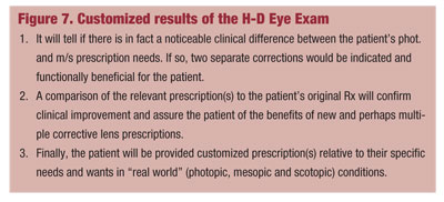
The results of the H-D Eye Exam customized, subjective assessment will yield three unique and valuable pieces of refractive information (figure 7).
The use of the H-D Eye Exam, in combination with the information from the Custom Wavefront Refraction, creates new and improved methods of analyzing and prescribing lower order lens correction through the analysis of lower order and higher order aberrations. This can only be achieved by the combined technological capabilities of wavefront aberrometry and electronic phoropters (figure 6).
Conclusion
The traditional refraction with a manual phoropter or autorefractor provides adequate lower order lens information for a given photopic or mesopic/scotopic (at which readings are captured) illumination level. This method, however, excludes distinct variables in the lower order prescription (particularly cylinder) created by changes in pupil diameter and subtle to significant changes produced by higher order aberrations at each level.
The use of wavefront aberrometry, encompassing autorefractive lower order readings with the effects of HOAs at multiple pupil diameters (Custom Wavefront Refraction) in conjunction with subjective refractive data comparisons of the resulting multiple prescription options (H-D Eye Exam) provides the most significant advance and refinement in refraction in over 100 years. These combined readings allow for the optimal prescribing and use of lower order lenses in individual and multiple prescriptions to correct human vision at typical and variable light (photopic) and dark (mesopic/scotopic) illuminated conditions.