Polish Your Dx SkillsNo matter how long you've been in practice, it's always worthwhile to brush up on your diagnostic techniques and incorporate newer ones when you can. This month in Review of Optometry, experts review how to refine your slit-lamp skills, distinguish between optic nerve differentials, use head-mounted perimetry and pay closer attention to detail in peripheral fundus photos. Check out the other articles featured in the February 2024 issue: |
The slit lamp biomicroscope is the fundamental diagnostic tool for ocular examination and proficiency in its use is crucial for developing expertise in eye care. The stereoscopic nature of the instrument permits three-dimensional visualization of the ocular anatomy, which allows for qualitative and quantitative analysis of various features. Beyond assessing pupil size, corneal thickness and anterior chamber depth, optometrists can use this tool to observe structures such as the adnexa, ocular surface, iris and crystalline lens.1 With the incorporation of handheld diagnostic lenses, not only can the posterior segment be evaluated but also the iridocorneal angle.
While you undoubtedly are familiar with the slit lamp, here we will explore methods you may not have previously thought of or attempted very often. Throughout, we will offer tips and share tricks to enhance your slit lamp skills in hopes of leading you to a more comprehensive examination.
Equipment and Set-up
The earliest slit lamp emerged in 1911 (offering monocular viewing only) and has undergone substantial modifications over the past century (Figure 1).1
The contemporary slit lamp biomicroscope consists of two principal components: the illumination system and the observation system. In today’s slit lamps, the illumination system can generate a uniform and aberration-free beam. The use of halogen bulbs may enhance the visualization of smaller structures for practitioners. The second component, the observation system, primarily pertains to magnification. Most modern slit lamps feature magnification systems ranging from 5x to 25x, although some models allow for up to 100x magnification.2
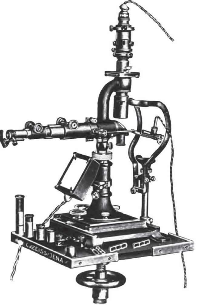 |
Fig. 1. The slit lamp has certainly evolved over the years. Here’s the original the instrument introduced in 1911 by Swedish ophthalmologist Allvar Gullstrand, who went on to win the Nobel prize for his many contributions to eye care. Click image to enlarge. |
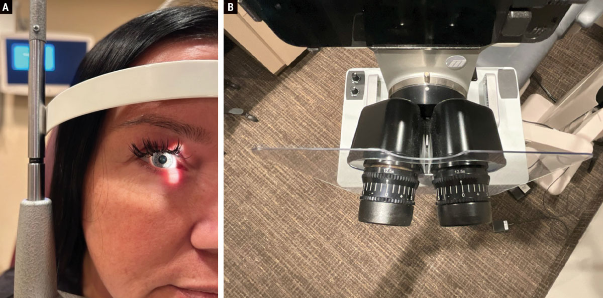
Prior to examination, ensuring the comfort and alignment of both the patient and the practitioner is crucial. Position the patient’s chin and forehead so that the canthus aligns with the eye mark on the post, as depicted in Figure 2a. The oculars should be adjusted to the correct pupillary distance and the eyepieces neutralized to account for the examiner’s prescription (Figure 2b). These factors will allow for a more comfortable and accurate viewing experience for both the doctor and patient.
Pro tip. Different body styles can sometimes be a challenge to position in the slit lamp. For those with a prominent bosom or abdomen, comfortable examination of these patients may prove difficult. To address this, elevate the examination chair to a higher position and instruct the patient to move forward in the seat, leaning into the slit lamp for a more comfortable examination.
 |
|
Fig. 2. (a) It is important to properly align the patient’s canthus with the mark on the slit lamp post. (b) The eyepieces should be neutralized for the examiner’s prescription and adjusted for their correct PD. Click image to enlarge. |
Choosing the appropriate slit lamp illumination and beam size is essential for achieving optimal visualization of the structures being examined.3 A longer and wider beam size is ideal for a thorough examination of specific structures like the lids, cornea, conjunctiva and sclera. Conversely, a fine, short beam size is more suitable for detailed viewing.
Commonly employed techniques include diffuse illumination, direct illumination (using methods such as parallelepiped, optic section, conical beam, specular reflection and tangential) and indirect illumination (involving techniques like retroillumination and sclerotic scatter). Each of these offers distinct advantages in visualizing different aspects of ocular structures, which are explained in detail ahead.
Pro tip. When inspecting the cornea, use the brightest illumination that the patient can comfortably tolerate. Many times, slight irregularities become apparent with just a slight increase in brightness (Figure 3).
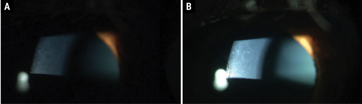 |
Fig. 3. ABMD in (a) dim illumination and (b) bright illumination at the slit lamp. Click image to enlarge. |
Next, let’s consider the three principal illumination methods with advice on performing various techniques.
Diffuse Illumination
This technique provides a comprehensive overview of the eye, emphasizing overall features rather than fine details. Primarily employed for a broad survey of the eye, it is effective for assessing corneal scars or infiltrations, identifying folds in Descemet’s membrane, detecting invading blood vessels in the cornea and observing edema of the epithelium, which appears hazy, gray and somewhat granular. To achieve this, set the angle between the slit lamp and the light source at 30° and 45°, use the widest slit and opt for low to medium magnification. Employ a diffusing filter for the widest slit width and maintain a medium to high illumination level (Figure 4).
 |
|
Fig. 4. Diffuse illumination allows for a broad overview of the eye rather than fine details. Click image to enlarge. |
Direct Illumination
This is the workhorse mode we optometrists tend to employ day in and day out. Several specific applications are discussed below.
Parallelepiped. This illumination technique is most effective when focusing on specific features and defects of the cornea. Parallelepiped illumination provides enhanced visualization of opaque features in the cornea such as scars, abrasions, nebulae, blood vessels and folds in Descemet’s membrane. These will reflect light and appear whiter than the surrounding areas. It is also advisable to examine these features under retroillumination.
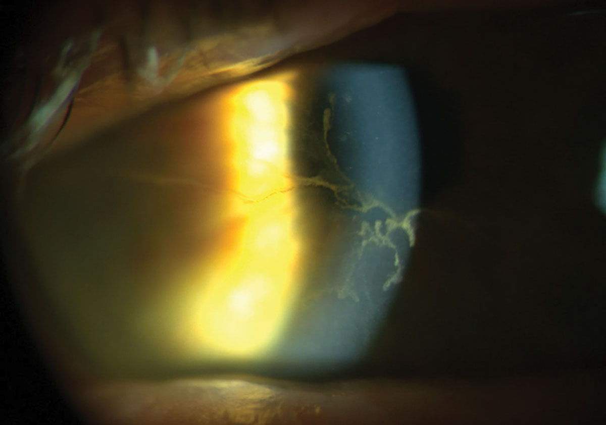
For a thorough assessment of corneal scarring or foreign bodies, higher magnification is preferred over the wide beam illumination, allowing for a detailed evaluation of both the depth and extent of these conditions. Corneal nerves, resembling fine white silk threads typically branching into a Y shape and mostly visible in the middle third of the stroma, become apparent under higher magnification (Figure 5). This technique is valuable for detecting corneal striae that develop in response to edema associated with contact lens wear, ocular surgery and keratoconus.
Moreover, the parallelepiped beam is instrumental in examining the endothelium. To achieve a parallelepiped, the beam width is narrowed to 1mm to 2mm, illuminating a rectangular area of the cornea. Position the microscope directly in front of the patient’s cornea with the light source approximately 45° from a straight-ahead position.
 |
|
Fig. 5. Paralellepiped illumination is most useful when focusing on specific features of the eye. Click image to enlarge. |
Optic section. Creating an optic section involves a very thin parallelepiped that optically cuts a minute slice of the cornea with maximum magnification. To achieve this, the slit length should be kept small. When examining anterior chamber depth, a wider slit width of 0.1mm to 0.3mm is recommended. The angle between the illuminating and viewing paths should be 45°, intersecting in the region of the anterior eye media under examination, such as the individual corneal layers.
This technique is employed to pinpoint and localize various features, including nerve fibers, blood vessels, infiltrates, cataracts and anterior chamber depth. It is particularly useful for identifying thickening, thinning and distortions in the corneal contour (Figure 6). Additionally, the optic section aids in determining the depth of foreign bodies or opacities within the corneal substance, expressed as a percentage of the total corneal thickness. To observe a wide slice of stroma, increase the angle between the microscope and illuminating arm.
Furthermore, the optic section can be valuable for perceiving flare in the aqueous. The luminous beam is directed in a way that the upper portion enters the lower part of the pupil, allowing the dark areas immediately above to serve as a contrasting background, enhancing visibility.
 |
|
Fig. 6. The optic section is commonly used to identify changes in the cornea as well as determining depth or location of a defect. Click image to enlarge. |
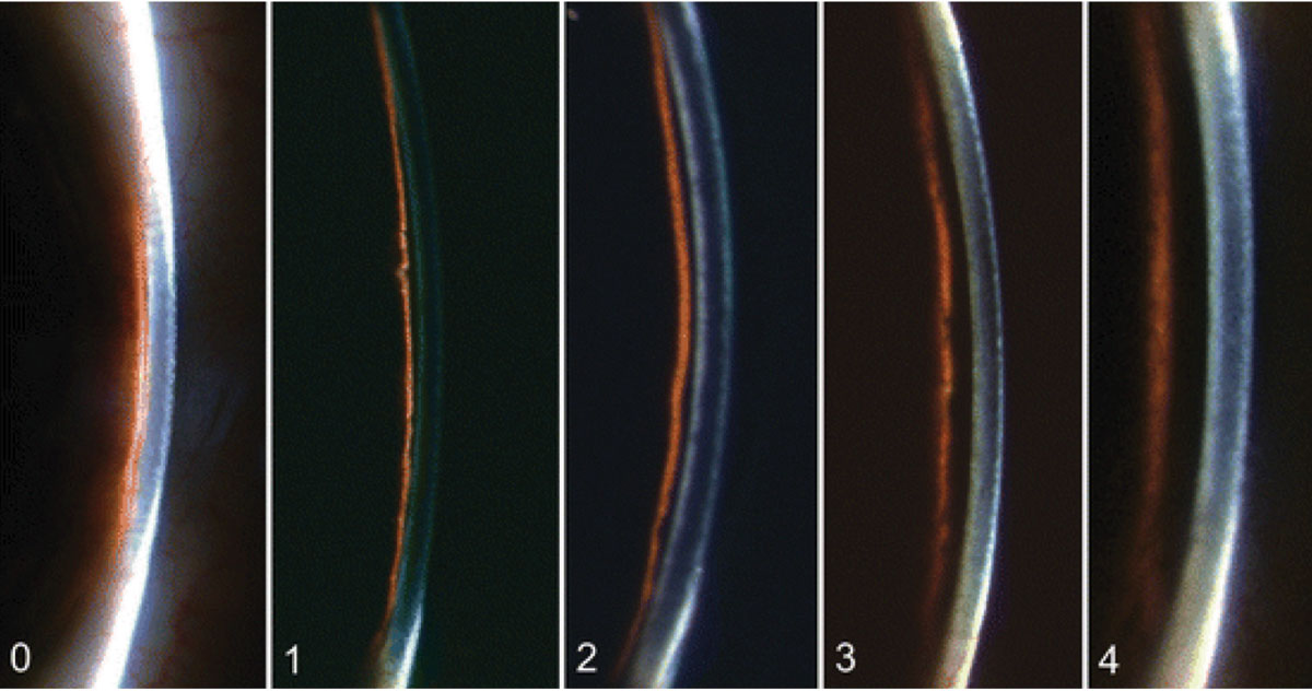
A very narrow optic section can also be used for the Van Herick method, which is used to assess the anterior chamber angle without using gonioscopy. It involves using medium magnification, directing a narrow beam close to the limbus at an angle of 60°. The evaluation is based on the depth of the anterior chamber in relation to the thickness of the cornea (Figure 7):
Grade 0: Closed anterior chamber, where the cornea “sits” on the iris.
Grade 1: Risky narrow anterior chamber angle with a ratio less than 1:4.
Grade 2: Narrow anterior chamber angle with a 1:4 ratio.
Grade 3: Open anterior chamber angle with a 1:2 ratio.
Grade 4: Open anterior chamber angle with a 1:1 ratio.
 |
|
Fig. 7. The Van Herick method assesses the depth of the anterior chamber in relation to the thickness of the cornea from grades 0 to 4, as pictured here. Click image to enlarge. |
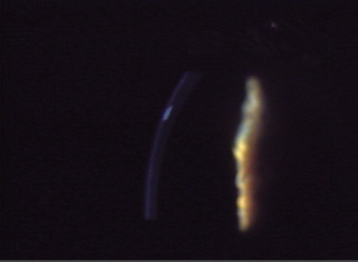
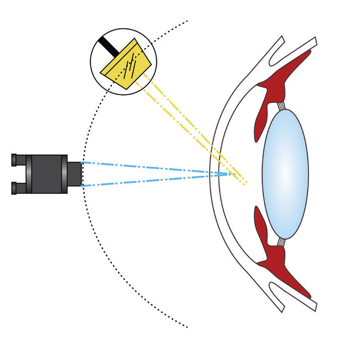
Conical beam. This light source is generated by reducing the vertical height of a parallelepiped to create a small circular or square spot of light. Position the light source to 45° to 60° temporally and direct into the pupil (Figure 8). Set the magnification to high (16x to 25x) and adjust the intensity of the light source to the highest setting. Focus the beam between the cornea and the anterior lens surface, with careful observation of the dark zone between the cornea and anterior lens. This technique is particularly valuable for examining the transparency of the anterior chamber to identify evidence of floating cells and flare, often observed in cases of anterior uveitis.
The Tyndall effect is the phenomenon that operates on the same principle as a beam of sunlight streaming through a room illuminating airborne dust particles. In the context of the eye, cells, pigment or proteins in the aqueous humor reflect light, creating a faint fog-like appearance. To visualize this phenomenon, the slit illuminator is adjusted to the smallest circular beam and projected through the anterior chamber from a 45° to 90-degree angle, with the strongest reflection occurring at 90°.
Pro tip. Once cells in the anterior chamber have been identified using a conical beam, elongate the beam to improve the differentiation between cells, pigment, blood, lens fragments or even foreign bodies. Cells in the anterior chamber can sometimes be confused with other elements, and a slight enlargement of the beam can assist in clearer differentiation.
 |
|
Fig. 8. An example of a conical beam. This light source is generated by reducing the vertical height of a papllelepiped to create a small circular or square spot of light. Click image to enlarge. |
Specular reflection. This viewing scenario is achieved by positioning the microscope and slit beam at equal angles, away from the normal positioning to the cornea. The light source is set at a 30-degree angle to one side and the microscope is placed at a 30-degree angle to the other side. The angles of the illuminator and microscope must be equal and opposite. Adjust the angle of the light until a bright reflex is obtained from the corneal surface, known as the zone of specular reflection. This technique is employed to assess the integrity of the corneal and lens surfaces. An even and regular reflection indicates a smooth surface, while irregularities, breaks or roughness will result in darker areas that fail to reflect light.
For visualizing the endothelium, initiate the process with lower magnification (10x to 16x), directing a relatively narrow beam onto the cornea. Transition to the highest available magnification and observe the endothelium using only one ocular. Under specular reflection, the anterior corneal surface appears as a white, uniform surface, while the endothelium exhibits a mosaic pattern.
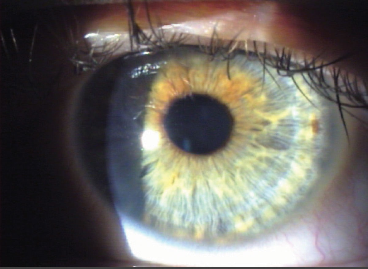
Tangential. This illumination method employs a medium-wide beam of moderate height. To implement this technique, swing the slit lamp arm to the side at an oblique angle, which necessitates a 90-degree separation between the illumination arm and the viewing arm. Magnifications of 10x, 16x or 25x are commonly applied. This method is used to observe both the anterior and posterior cornea and provides an optimal view of the iris without dilation. It is particularly useful for examining the anterior lens, making it an effective approach for viewing conditions like pseudoexfoliation.
Pro tip. Frequently, it is advisable to use a combination of illumination techniques. Corneal lesions, including nodules, foreign bodies, scars and the like, can be readily identified by employing sclerotic scatter and a broad parallelepiped beam. Subsequently, examining the same lesion with an optic section is recommended to help determine its depth.
Indirect Illumination
Lesions that are more subtle, refractile and/or transparent are usually revealed better via indirect illumination techniques.
Sclerotic scatter. Achieving this technique involves directing a bright yet narrow beam onto the limbus. With low 10x magnification and an angle of 40° to 60°, aligning the microscope correctly reveals a ring of light surrounding the cornea, effectively highlighting any corneal pathology. The microscope is directed straight ahead, and when the light is appropriately aligned with respect to the eye, a distinct ring of light becomes visible around the cornea. This light is absorbed and scattered through the cornea, accentuating pathology for a detailed examination.
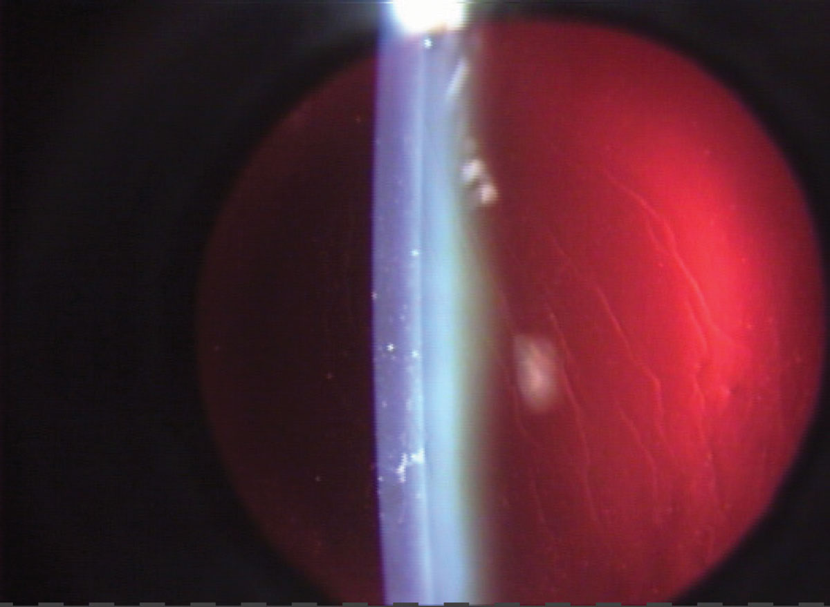
Retroillumination. Reflecting light from a slit beam off a structure situated more posterior than the one under observation will create retroillumination. A vertical slit beam, typically 1mm to 4mm wide, is commonly employed. This technique is frequently used to identify keratic precipitates and other debris on the corneal endothelium (Figure 9). Additionally, retroillumination can be applied to view water clefts, vacuoles of the anterior lens and posterior subcapsular cataracts in the crystalline lens.
 |
|
Fig. 9. Retroillumination from the fundus will highlight different corneal changes. Click image to enlarge. |
Direct retroillumination from the iris involves using a magnification of 16x to 25x and directing the light from a 45-degree angle. Position the microscope straight ahead to observe corneal pathology. Direct a moderately wide slit beam toward the iris directly behind the corneal anomaly. Indirect retroillumination from the iris follows a similar process, but the beam is directed to an area of the iris bordering the portion behind the pathology. This method provides a dark background, enhancing the contrast for viewing corneal opacities and other details such as the angles.
Retroillumination from the fundus involves placing the slit illuminator in an almost coaxial position with the biomicroscope. Shorten the slit beam—angled at 2° to 4°—to the height of the pupil to prevent reflection of bright light off the iris. The decentered slit beam is projected near the pupil margin through a dilated pupil. Focus the microscope directly on the pathology using 10x to 16x magnification and opacities will appear in silhouette.
Transillumination. With the pupil in a state of mid-mydriasis (3mm to 4mm when light stimulated), transillumination of the iris becomes possible. Align the light source coaxially (directly in line) with the microscope and employ a full-circle beam of light equivalent to the size of the pupil. Project the light through the pupil and into the eye, focusing the microscope on the iris; a magnification of 10x to 16x is sufficient. The evaluation of the iris involves assessing how light passes through it, leveraging the red reflex. Normally, the iris pigment absorbs the light; however, pigmentation defects allow the red fundus light to pass through.4,5
Pro tip. Establish a methodical protocol for patient exams to minimize the risk of overlooking any structures or disease states. Irrespective of the exam’s purpose, our standardized procedure involves inspecting the lids, lashes, conjunctiva, corneal epithelium to endothelium, anterior chamber, iris with transillumination, lens from anterior to posterior and concluding with an examination of the anterior vitreous prior to use of handheld diagnostic lenses.
 |
|
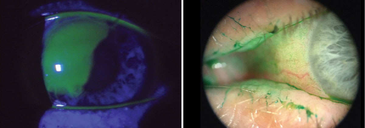
Fig. 10. The use of vital dyes is imperative when assessing the ocular surface for signs of infection, trauma, surface abnormalities among others. Using the cobalt blue filter in conjunction with sodium fluorescein will highlight certain corneal abnormalities. Lissamine green tends to highlight dead and degenerating cells. It will also easily adhere to mucus strands and filaments and even show advanced conjunctival staining in dry eye patients. Click image to enlarge. |
Takeaways
In conclusion, the slit lamp biomicroscope stands as the cornerstone of ocular diagnostics, playing a pivotal role in comprehensive eye care. Mastery of this instrument is essential for optometrists, as it enables a three-dimensional visualization of the anterior segment, allowing for both qualitative and quantitative analysis of various ocular features. The evolution of the slit lamp over the past century has equipped practitioners with advanced illumination and observation systems, enhancing the ability to visualize minute structures and abnormalities.
Continuous exploration and refinement of slit lamp skills are paramount. By embracing these techniques, you can deepen your understanding of ocular pathology, improve diagnostic accuracy and ultimately elevate the standard of care provided to your patients.
Dr. Colatrella is the medical director and owner of PineCone Vision Center in Sartell and St. Cloud, MN. He is a fellow in the American Academy of Optometry, past chair of its disease section and a founding chair of the anterior segment section as well as one of the first of two diplomates in anterior segment disease. Dr. Varanelli practices at Simone Eye Center in Warren, MI, where he specializes in comprehensive eye care with an emphasis on the medical and surgical comanagement of eye disease. He is a Fellow of the American Academy of Optometry and a past chair of its anterior segment section.
1. Kaur K, Gurnani B. slit lamp biomicroscope. In: StatPearls [Internet]. Treasure Island (FL): StatPearls Publishing. June 11, 2023. Accessed January 23, 2024. www.ncbi.nlm.nih.gov/books/NBK587440/. 2. Kalayoglu MV. The evolution of slit lamp biomicroscopy. November 30, 2005. Accessed January 25, 2024. www.ophthalmologyweb.com/tech-spotlights/26450-the-evolution-of-slit-lamp-biomicroscopy/. 3. Martin R. Cornea and anterior eye assessment with slit lamp biomicroscopy, specular microscopy, confocal microscopy and ultrasound biomicroscopy. Indian J Ophthalmol. 2018;66(2):195-201. 4. Scott A. Introduction to slit lamp utilization. Canadian Association of Optometrists. April 10, 2019. Accessed January 23, 2024. https://srpc.ca/resources/documents/RR/2019/syllabus/handouts/333.pdf. 5. Jacobs N. Advanced slit lamp skills. March 3, 2015. Accessed January 23, 2024. www.healthpartners.com/institute/wp-content/uploads/2018/05/3-SA-45-SLE-Handouts-new.pdf. |
